
 EN
Quick answer: which metal manufacturing process should you choose?
Choose deep drawing when the part needs a seamless cup, shell, tank, can, cover or other hollow shape formed from a flat blank. Choose progressive die stamping when the design is a repeatable flat or formed component and the production volume justifies dedicated tooling. Choose sheet metal fabrication when you need flexible prototyping, laser-cut profiles, formed enclosures, welded assemblies or a process route that can change as the design develops.
The best process is not selected by material name alone. The decision depends on the part geometry, wall depth, bend and corner requirements, annual quantity, tolerance-critical features, surface finish, tooling budget and delivery stage. A useful manufacturing review therefore compares the drawing against the process before quoting the tooling or production price.
For a practical starting point, review Deeplink’s custom sheet metal fabrication service, metal stamping parts, metal deep drawing service and metal fabrication tolerances guide. These pages cover the individual routes; this guide connects them into one selection framework.
What is the difference between the three processes?
Deep drawing: seamless hollow parts from sheet metal
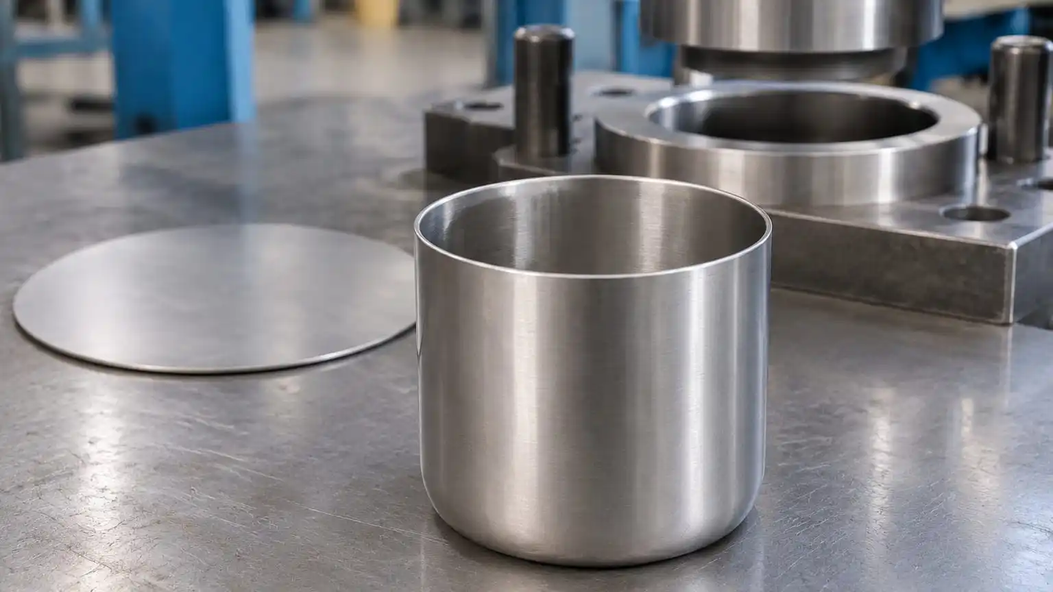
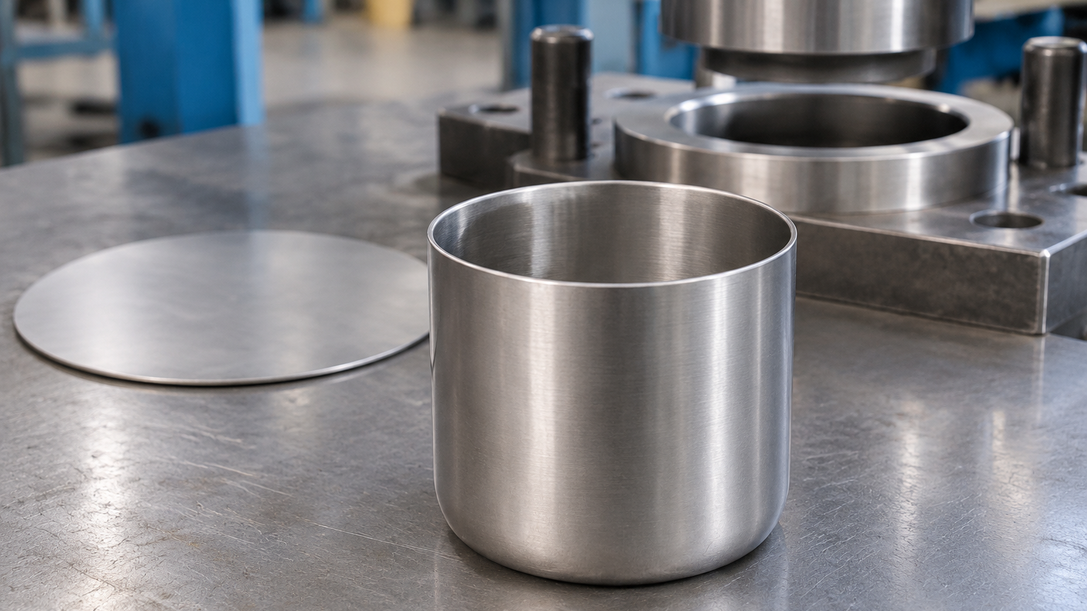
A circular blank can be formed into a seamless hollow cup; geometry and material determine the tooling route.
Deep drawing uses a punch and die to pull a flat metal blank into a cavity. The result can be a cylindrical, rectangular or otherwise shaped hollow part with fewer joints than an assembly made from several cut and welded pieces. Typical applications include containers, covers, housings, tanks and drawn shells where continuity of the material is important.
Deep drawing is strongly affected by material formability, blank size, wall thickness, corner radius, lubrication, draw depth and the number of forming stages. Stainless steel grades, aluminum grades and carbon steel do not behave identically. Deeplink’s metal materials guide explains why 304 and 316 stainless steel, 5052 and 6061 aluminum, carbon steel, copper and brass should be selected with the forming route and finish in mind.
The process is usually a good candidate when a drawing calls for a repeatable hollow form, a clean internal volume or a reduced number of welded seams. It is less attractive when the design changes frequently, the quantity is too low to spread tooling cost, or the geometry is better made as a cut, bent and welded assembly.
Progressive die stamping: repeatable parts at production volume
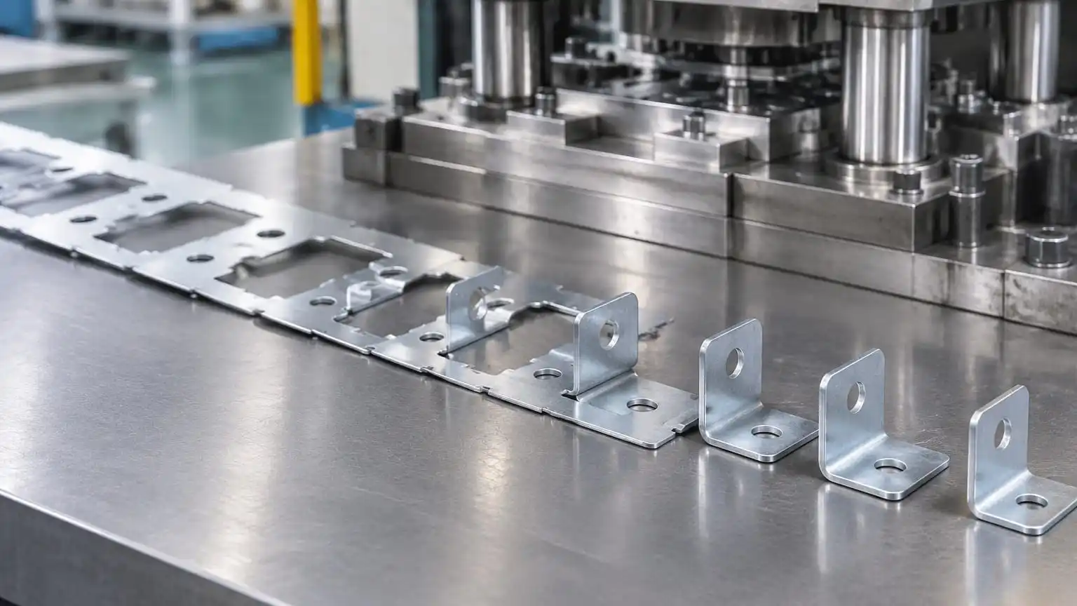
A progressive-die concept: several operations turn a continuous strip into repeatable formed brackets.
Progressive die stamping feeds strip or coil material through a sequence of stations. Each station performs an operation such as blanking, piercing, bending, embossing or forming. The finished component leaves the die after several operations, which makes the method efficient for repeatable parts and high production volumes.
The main advantages are cycle efficiency, repeatability and the ability to combine multiple operations in one controlled tool. The trade-off is the engineering and tooling investment required before production. Strip layout, carrier design, material utilization, die maintenance and first-article approval all affect the total cost of the programme.
Progressive stamping is often appropriate for brackets, clips, terminals, reinforcement parts, retainers and other components that repeat thousands of times. It is not automatically the cheapest option for a prototype or a small batch. When the part design is still moving, a laser-cut and formed sample may provide faster feedback before a production die is released.
Sheet metal fabrication: flexible cutting, forming and joining
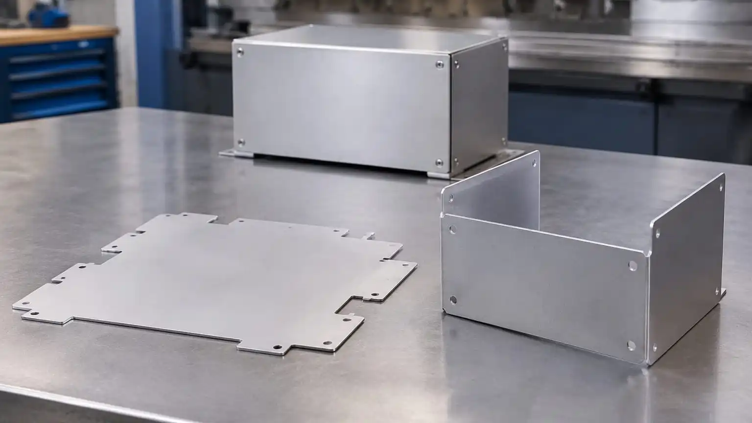
A fabricated enclosure route can combine cut blanks, formed flanges and a finished assembly.
Sheet metal fabrication combines operations such as laser cutting, punching, bending, welding, riveting, finishing and assembly. It is a flexible route for prototypes, low-to-medium volume production, enclosures, brackets, frames and assemblies made from several features or panels.
The advantage is design flexibility. A manufacturer can review the drawing, cut a profile, form it on a press brake, weld or rivet subcomponents and adjust the design without rebuilding a complex progressive die. The trade-off is that the result may include bends, seams, welds or assembly steps that would not exist in a single drawn or stamped component.
A strong sheet metal programme still needs process discipline. The drawing should identify material, thickness, bend direction, critical dimensions, finish and any masked areas. Deeplink’s sheet metal fabrication tolerances guide explains why a tolerance should describe what a process can hold repeatably, not an isolated best result.
Process selection table for OEM buyers
| Decision factor | Deep drawing | Progressive stamping | Sheet metal fabrication |
|---|---|---|---|
| Best geometry | Hollow, seamless or shell-like forms | Repeatable flat or formed components | Panels, brackets, enclosures and assemblies |
| Best production stage | Validated design moving to repeat production | Stable design with production volume | Prototype through flexible production |
| Tooling profile | Dedicated punch and die; stages may be required | Dedicated progressive die with multiple stations | Lower dedicated tooling; process-specific fixtures may apply |
| Design changes | More expensive after tooling is released | More expensive after die release | Generally easier during development |
| Typical cost driver | Draw stages, material behavior, tooling and scrap | Die complexity, strip layout, tool maintenance and volume | Cutting time, bends, welding, finishing and assembly |
| Important inputs | Material, thickness, depth, radius and formability | Strip width, pitch, feed, features and annual volume | Flat pattern, bend data, joints, finish and assembly needs |
| Quality focus | Depth, diameter, wall condition and first article | Feature location, burrs, forming and die repeatability | Cut edge, bend angle, welds, assembly and final dimensions |
This table is a screening tool, not a substitute for an engineering review. A drawing may combine processes: laser cutting and bending for a prototype, progressive stamping for a bracket programme, or deep drawing followed by trimming, piercing, welding or machining for a finished component.
How annual volume changes the decision
Prototype and low-volume parts
For a prototype, the priority is usually learning speed rather than the lowest theoretical piece price. Sheet metal fabrication can often provide a cut-and-formed sample quickly, allowing engineers to check fit, clearance, bend sequence, assembly and finish. CNC machining may also be suitable when the part is thicker or when a critical feature cannot be produced economically through sheet forming.
Deep drawing can still be used for a prototype, but the team should understand which tooling is temporary, which dimensions are being validated and whether the final production route will change. A prototype made by one process is not automatically proof that the same geometry is ready for a production die.
Repeated production and high-volume parts
When demand is stable, progressive stamping can spread tooling cost across a large quantity and improve cycle efficiency. Deep drawing can provide the repeatability of a formed shell when the part geometry and material route have been validated. A proper cost comparison should include tooling amortization, scrap, secondary operations, inspection, maintenance and logistics rather than comparing only the quoted piece price.
Volume alone does not make a process correct. If the design has tight machining features, complex weldments or frequent engineering changes, a flexible route may remain more practical. The correct decision is the route that meets function and quality requirements with a total cost that remains predictable over the programme life.
How material, thickness and finish affect process choice
Material should be evaluated together with thickness and finish. For example, 304 stainless steel is often selected for its balance of corrosion resistance, formability and weldability. 316 stainless steel can be more appropriate when chloride or marine exposure is a significant concern. Aluminum 5052 is commonly considered for formed parts, while 6061 is often selected when machining and higher strength are more important. These are starting points, not universal substitutions.
Thickness changes forming force, bend behavior, weld heat input and dimensional response. Surface finish can also affect the result: brushing, anodizing, plating and powder coating may change appearance, corrosion resistance, masking requirements or final dimensions. The drawing should therefore state the material grade, thickness range, finish and any cosmetic surface requirement.
When the specification is incomplete, provide the application, load, operating environment, expected quantity and assembly conditions. Deeplink’s materials guide can be used as a pre-quotation reference, while the engineering team should confirm the final grade and process against the drawing.
How DFM review prevents expensive process changes
Design for manufacturability review should happen before tooling starts. The review asks whether the selected process can produce the geometry repeatedly, whether tolerances are assigned only where function requires them, and whether material flow, bend access, weld access, inspection and finishing are practical.
For deep drawing, the review should consider draw depth, radii, transitions, blank development, potential wrinkling or thinning and whether multiple draw operations are needed. For progressive stamping, it should examine strip direction, carrier points, pierce and form sequence, burr orientation, die access and maintenance. For sheet metal fabrication, it should check bend reliefs, minimum flange lengths, hole-to-edge distances, bend sequence, weld distortion and the flat pattern.
A useful drawing package includes a 2D drawing with tolerances and critical dimensions, a 3D model for geometry reference, material and thickness, expected quantity, finish requirements and the dimensions that affect assembly. Deeplink’s quality assurance and inspection page describes incoming material, first-article, in-process and final inspection as part of its production quality workflow.
How to prepare a custom metal parts RFQ
A quote becomes more useful when the buyer sends enough information to compare process routes rather than asking for a unit price from an incomplete image. Include:
- The 2D drawing with units, datums, tolerances and critical-to-function dimensions.
- The 3D CAD model in the native or agreed exchange format.
- Material grade, thickness and acceptable substitutions, if any.
- Prototype quantity, production quantity and expected repeat order pattern.
- Surface finish, coating, plating, brushing or cosmetic requirements.
- Assembly requirements, inserts, welds, rivets, hardware and masked areas.
- Inspection documents, material certificates or first-article requirements.
- Packaging, delivery destination and any customer-specific labelling.
If the design is not final, say which dimensions are still under review. It is better to receive a process recommendation with clear assumptions than a price that hides tooling, finishing or inspection risk. You can send the package through Deeplink’s contact and quote page for a manufacturing review.
FAQ: deep drawing, stamping and sheet metal fabrication
Is deep drawing better than stamping?
Neither process is automatically better. Deep drawing is usually better suited to seamless hollow or shell-like parts. Progressive stamping is usually better suited to repeatable flat or formed components produced at volume. The drawing, material, quantity and tooling economics determine the fit.
Is progressive stamping suitable for prototypes?
It can be, but it may not be the most economical first route when the design is changing or the quantity is small. A laser-cut and formed prototype can provide faster design feedback before a progressive die is finalized. The production route should be confirmed after the prototype requirements are understood.
Can sheet metal fabrication be used for high-volume production?
Yes, especially for enclosures, brackets, frames and assemblies where cutting, bending, welding and finishing can be balanced effectively. For very repeatable components, progressive stamping or deep drawing may provide a better production model. A process comparison should include total programme cost and quality requirements.
Which material is best for deep drawn parts?
The best material depends on the required formability, corrosion resistance, strength, thickness and finish. 304 stainless steel, 316 stainless steel, selected aluminum grades and carbon steels may all be suitable in different designs. Confirm the grade and draw route through a drawing review rather than choosing by material name alone.
What should I do if the drawing has very tight tolerances?
Mark the dimensions that affect fit, function or sealing, and avoid applying the same tight tolerance to every feature. Process capability, material behavior and inspection method should be reviewed together. Deeplink’s tolerance guide explains the process-level figures published for its fabrication and machining work.
Final recommendation
Start with the part function and geometry, then compare annual volume, material behavior, tooling investment, tolerance-critical features, finish and change frequency. Use sheet metal fabrication when flexibility and fast design feedback matter; use deep drawing for seamless formed shells; use progressive stamping for stable, repeatable components at production volume. In many real programmes, the best answer is a staged route: fabricate a prototype, complete DFM and first-article validation, then move the stable design into a dedicated forming or stamping process.
For a drawing-based recommendation, contact Deeplink with the part file, material, quantity, finish and critical dimensions. A manufacturing review should explain not only what the part may cost, but also why the chosen process is repeatable.
Table of Contents
- Quick answer: which metal manufacturing process should you choose?
- What is the difference between the three processes?
- Process selection table for OEM buyers
- How annual volume changes the decision
- How material, thickness and finish affect process choice
- How DFM review prevents expensive process changes
- How to prepare a custom metal parts RFQ
- FAQ: deep drawing, stamping and sheet metal fabrication
- Final recommendation