
 EN
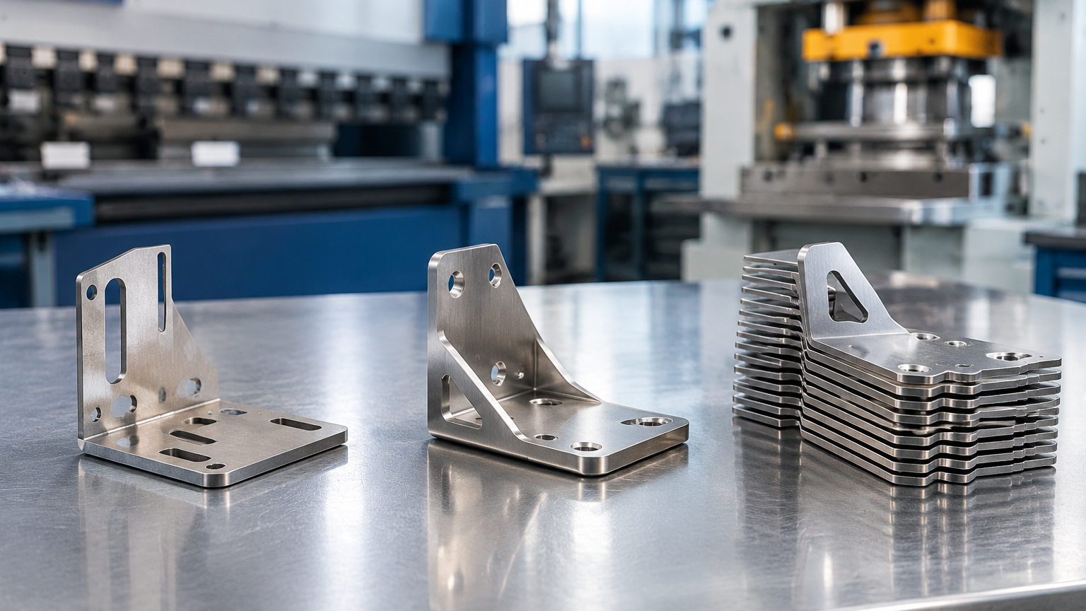
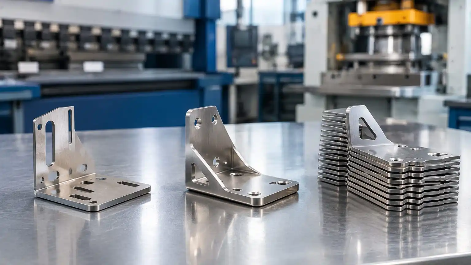
Three stages of a custom metal component programme: flexible prototype fabrication, DFM-refined pre-production forming, and repeatable volume production.
Quick answer: how does DFM lower total cost from prototype to production?
Design for Manufacturability (DFM) reduces custom metal part cost by aligning part geometry, material grade, bend radii, hole locations, weld joints and critical tolerances with the actual production route before dedicated tooling or repeat batches are released. In OEM sheet metal and stamping programmes, most avoidable unit-cost increases and schedule delays come from five issues: tight blanket tolerances applied to non-critical features, holes placed too close to bend lines, missing bend reliefs, material grades mismatched to forming depth or corrosion exposure, and prototype designs that cannot transition cleanly into progressive stamping or deep drawing.
Running a structured DFM check at the prototype stage lets engineering teams validate fit and function quickly with custom sheet metal fabrication, then scale into metal stamping parts or metal deep drawing service without redesigning the mating assembly. If you are still deciding between forming routes, read our companion guide on deep drawing vs progressive stamping vs sheet metal fabrication alongside this DFM checklist.
Why prototype parts fail when scaling to volume production
What works on a laser cutter and press brake may not work in a die
During early prototyping, a fabricator can laser-cut complex contours, form tight flanges through manual stage bending, TIG-weld corner seams and hand-deburr edges to deliver functional samples. That flexibility is ideal for design verification, but it can hide geometry traps that become expensive at 5,000 or 50,000 pieces per year.
When a part moves from low-volume press-brake bending to progressive die stamping or deep drawing, strip carrier layout, coil grain direction, punch access, springback control and burr direction become hard constraints. A feature that took two minutes of manual grinding on a five-piece prototype can become a secondary machining bottleneck or a die-maintenance risk in mass production.
The hidden cost of freezing drawings before a manufacturing review
Many engineering teams freeze 2D drawings immediately after the first physical prototype passes mechanical fit checks. If the drawing locks in sharp internal corner radii, zero-clearance fastener holes or unnecessary cosmetic weld grinds, suppliers are forced to quote slower processes or add secondary fixtures. Reviewing manufacturability before drawing freeze allows minor geometry adjustments—such as widening a bend relief, standardizing inside bend radii across all flanges, or opening non-critical tolerances—that preserve function while cutting cycle time and scrap.
Core geometry rules for sheet metal and stamped parts
Bend radius, bend relief and flange length rules
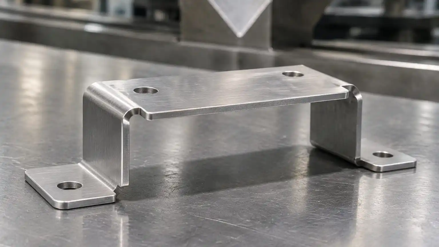
Clean bend relief notches and proper hole setback prevent corner tearing and hole ovality during press-brake forming or stamping.
Every sheet metal bend stretches the outer surface and compresses the inner surface. When a bend meets an adjacent unbent edge without clearance, the metal pinches and tears at the corner. Adding a bend relief notch—wider than the tooling clearance and deeper than the inside bend radius plus material thickness—allows the flange to fold cleanly without corner cracking.
Standardizing inside bend radii is equally important. Using a single consistent inside bend radius across a part lets the shop run fewer press-brake tool setups or simpler die stations. Short flanges should also be checked against V-die opening width: if a flange is shorter than the minimum die support span, it cannot be formed safely on a standard press brake without special tooling or excess sacrificial stock.
Hole-to-bend and hole-to-edge distance guidelines
Holes, slots and louvers placed too close to a bend line will deform into teardrops or ovals as the metal flows around the punch radius. When fastener holes distort, operators must either ream the holes after forming or laser-cut them in a secondary fixture—both of which add cost and dimensional variation.
To avoid hole distortion during forming:
- Keep round mounting holes and tapped extrusions outside the bend deformation zone (determined by material thickness and inside bend radius).
- If a feature must sit near a bend line for compact packaging, discuss a relief slot on the bend line or a post-form piercing station in a progressive die.
- Maintain sufficient web width between holes and outer cut edges so piercing punches do not bulge the perimeter or cause premature die wear.
Designing tabs, slots and weld seams for self-fixturing assemblies
When an enclosure or chassis requires welded subcomponents, welding labor and heat distortion often dominate the unit price. Incorporating tab-and-slot self-fixturing features into the flat laser-cut blank allows parts to locate themselves accurately before tack welding. Self-fixturing geometry reduces custom welding jig costs, speeds up operator setup and improves part-to-part repeatability across batches.
How to match material grades to forming, corrosion and finish requirements
Comparing 304 vs 316 stainless steel, 5052 vs 6061 aluminum, and carbon steel
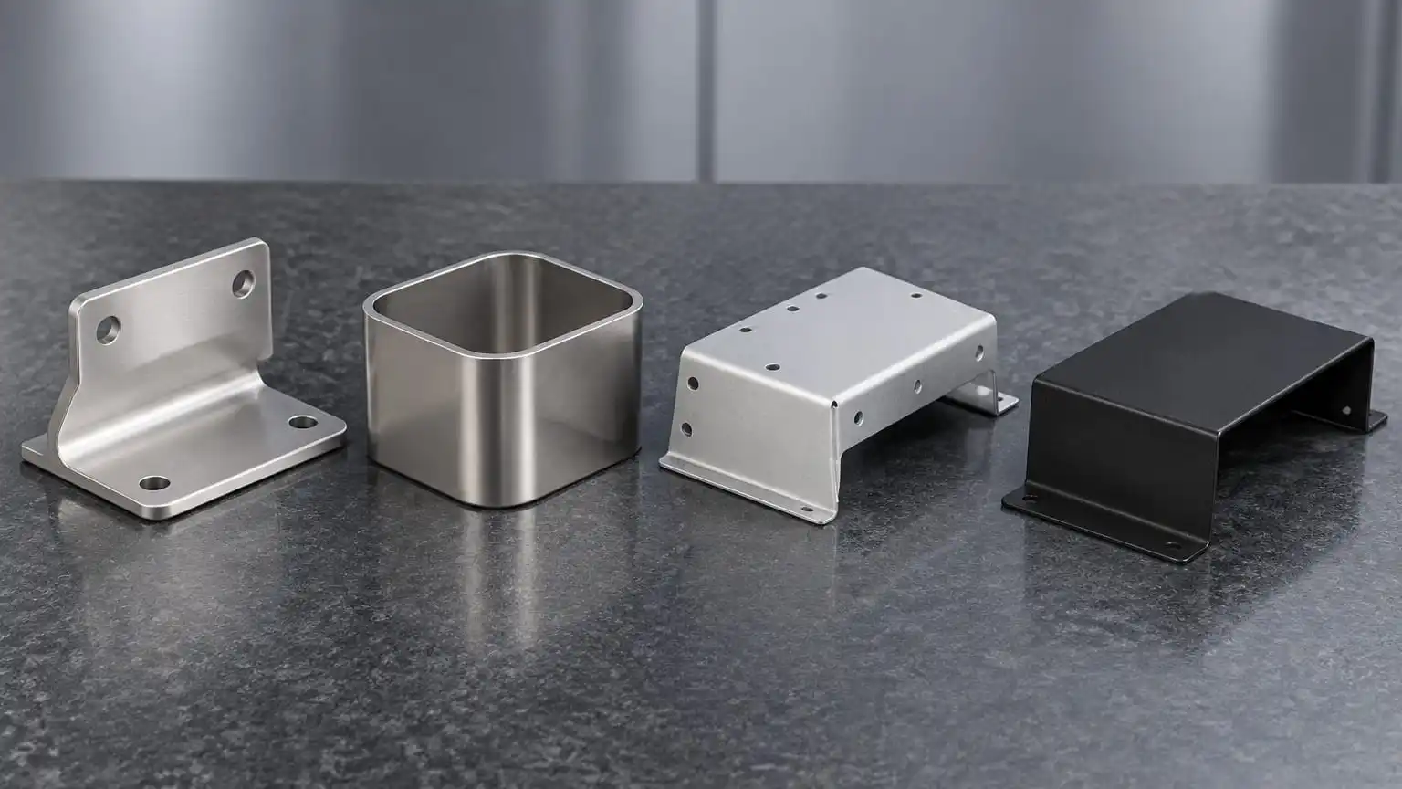
Material selection balances formability, corrosion resistance and surface finish across stainless steel, aluminum and coated carbon steel routes.
Choosing a metal grade solely by tensile strength or raw material price frequently leads to cracking during bending or premature corrosion in service. Engineers should evaluate formability, weldability and finish compatibility together using Deeplink’s metal materials guide:
- 304 stainless steel: Offers strong general corrosion resistance, good elongation for deep drawing and bending, and reliable TIG or laser weldability. Widely used for industrial enclosures, food-contact covers and drawn shells.
- 316 stainless steel: Adds molybdenum for improved resistance to chlorides, salt spray and chemical washdowns. Preferred for marine, medical and harsh outdoor hardware, though its work-hardening behavior requires careful tooling and lubrication control.
- 5052 aluminum vs 6061 aluminum: 5052 is typically far better suited to tight sheet-metal bending and forming without outer-radius micro-cracking. 6061 offers higher strength and excellent machinability for CNC components, but in standard heat-treated tempers it is prone to cracking on tight sheet-metal bends.
- Carbon steel (such as SPCC or Q235) with protective finish: Cost-effective and highly formable for internal brackets, frames and cabinets, provided the drawing specifies zinc plating, e-coating or powder coating to prevent rust.
Accounting for coating buildup on mating features and threads
Powder coating, electroplating, anodizing and passivation change surface thickness and friction. If a drawing specifies tight pin holes, sliding rails or threaded inserts without stating whether dimensions apply before or after surface treatment, assembly fit issues are almost guaranteed. Always note on the 2D drawing which surfaces require masking, which threads must stay free of powder buildup, and whether critical tolerances are measured pre-plate or post-coat.
DFM & prototype-to-production decision matrix for OEM engineers
| Engineering dimension | Prototype & low-volume priority | Volume production priority | High-risk DFM mistake to avoid | Practical engineering fix |
|---|---|---|---|---|
| Process route | Laser cutting, CNC press brake, TIG/laser welding | Progressive die stamping, transfer stamping or deep drawing | Designing a prototype geometry that cannot be fed on a strip or drawn in a cavity | Review long-term annual volume during prototype DFM so geometry supports future tooling |
| Bend & corner design | Standard V-die radii and laser-cut corner reliefs | Uniform radii, balanced forming forces and controlled springback | Sharp zero-radius internal corners or missing bend reliefs at flange intersections | Specify uniform inside bend radii and add explicit relief notches on the flat pattern |
| Holes & fasteners | Laser-cut holes, PEM hardware or tapped holes | In-die piercing, extruded holes or automated hardware insertion | Placing critical holes inside the bend zone where metal stretches | Move holes away from bend lines or use slots/relief cuts where packaging is tight |
| Material grade | Readily available stock thickness and standard alloy | Coil-compatible alloy with consistent elongation and temper | Specifying 6061-T6 for tight sheet-metal bends or omitting temper requirements | Pair formed sheet parts with formable grades (such as 5052 aluminum or 304/316 stainless) |
| Tolerance allocation | Manual caliper, height gauge and mating fit check | Gauge repeatability, fixture inspection and statistical process stability | Applying tight machining tolerances (such as ±0.05 mm) across an entire welded sheet frame | Isolate critical-to-function (CTF) datums and use standard fabrication tolerances elsewhere |
| Surface finish | Basic deburring, brushing or sample batch coating | Automated pretreatment, racked coating and defined masking zones | Leaving cosmetic A-surfaces and thread masking undefined on the drawing | Mark A/B/C cosmetic surfaces and specify pre-coat vs post-coat dimensional callouts |
How to set realistic tolerances and inspection checkpoints
Separating critical-to-function (CTF) dimensions from general profile tolerances
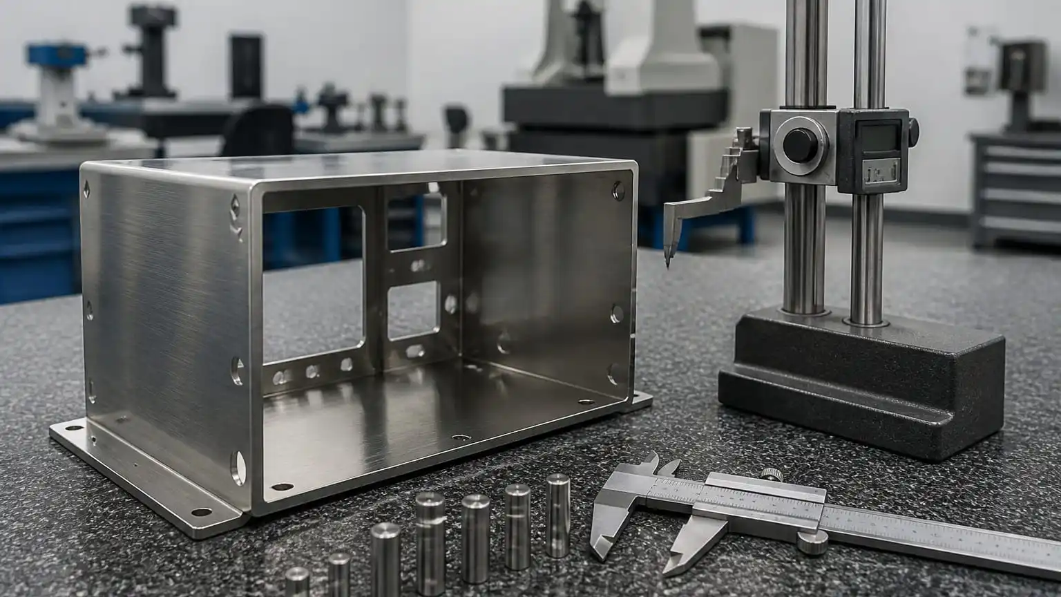
First-article inspection verifies critical-to-function datums, hole positions and formed dimensions against the engineering drawing.
One of the fastest ways to inflate a custom metal quote is to copy a tight title-block tolerance from a CNC machined part onto a multi-bend sheet metal weldment. Sheet metal cutting, press-brake forming, stamping and welding each have distinct capability ranges influenced by material thickness, thermal expansion and springback.
Before releasing a drawing, review Deeplink’s metal fabrication tolerances guide. Call out tight tolerances only on critical-to-function (CTF) interfaces—such as bearing bores, connector cutouts, sealing surfaces or mounting hole patterns—and allow standard process tolerances on non-mating outer profiles. Where ultra-tight flatness or bore concentricity is mandatory on a formed or welded part, plan for a secondary CNC machining operation after forming or stress relief.
Aligning First Article Inspection (FAI) with production gauges
A drawing tolerance is only meaningful if both buyer and supplier agree on how it is measured. Flexible thin-wall sheet metal parts can flex under clamping pressure or gravity, causing two inspectors to record different readings on the same part.
During quality assurance and inspection planning, define:
- Primary datum surfaces that represent how the part mounts in the final product.
- Restrained vs free-state measurement for thin-gauge enclosures, deep-drawn shells and long channels.
- Go/No-Go pin or check-fixture verification for high-volume stamped brackets so in-process quality checks match First Article Inspection (FAI) standards.
Step-by-step RFQ & DFM package checklist for faster quoting
To get an accurate DFM review and a transparent comparison between prototype and production pricing, send a complete technical package through Deeplink’s contact and quote page:
-
3D CAD model (
STEPorIGES) for exact flat-pattern unfolding, bend simulation and tooling layout. -
2D engineering drawing (
PDForDXF) showing units, datum references, critical-to-function (CTF) tolerances, thread callouts and hardware specs. - Material specification and thickness (including alloy grade, temper if applicable, and whether equivalent mill standards are acceptable).
- Prototype quantity vs estimated annual volume (EAU) so engineers can compare soft-tooled fabrication against progressive stamping or deep drawing.
- Surface treatment and cosmetic criteria (brushing grain direction, plating standard, powder coat color/texture, salt-spray requirement and masked zones).
- Welding and assembly instructions (structural vs cosmetic welds, leak-tightness requirements, PEM nut/stud part numbers and subassembly packaging).
- Quality documentation requirements (material mill certificates, RoHS/REACH compliance, First Article Inspection report or CMM dimensional data).
FAQ: custom sheet metal DFM and scaling to production
When should we switch from laser cutting and bending to progressive stamping?
The transition point depends on part complexity, number of bends, secondary hardware and annual demand. When order quantities become regular and stable, progressive stamping can reduce unit labor cost and improve feature-to-feature repeatability by combining piercing, forming and blanking into one continuous die. A proper DFM review compares total programme cost—including die amortization, material utilization and lead time—rather than looking at piece price alone.
Why do holes near bend lines deform in sheet metal parts?
When sheet metal is bent on a press brake or forming die, material near the bend radius undergoes plastic stretching and compression. Any hole or slot located inside that deformation zone is pulled out of round. Moving the hole outside the minimum bend setback, adding a relief slot at the bend line, or piercing the hole after forming prevents fastener misalignment.
Can 6061 aluminum be used for tight sheet metal bends?
6061 aluminum in its common heat-treated temper (such as T6) has lower ductility than 5052 aluminum and is prone to cracking along the outer bend radius when formed into tight 90-degree bends. Unless the part requires heavy CNC machining or specific structural properties with large bend radii, 5052 aluminum is generally the safer choice for formed sheet metal enclosures and brackets.
How do surface coatings affect tight sheet metal tolerances?
Electroplating, e-coating and powder coating add measurable layer thickness to edges, holes and threads. Without explicit drawing notes, a hole that passes inspection in bare metal may become undersized after powder coating. Specify whether tight tolerances apply before or after coating, and mark ground studs, mating faces and tapped holes that require masking or post-coat chasing.
What is the best way to avoid welding distortion on thin stainless steel enclosures?
Minimize continuous heavy weld beads where intermittent tack welds or laser welds can meet structural requirements, use self-locating tab-and-slot joints to hold geometry in a fixture, and balance heat input symmetrically. When a seamless hollow geometry can eliminate corner welds altogether, evaluate whether deep drawing is a better long-term production route.
Final recommendation
Treat DFM as a bridge between prototype speed and production economics. Before locking your 2D drawing or funding hard tooling, review bend reliefs, hole setbacks, alloy formability, coating buildup and critical-to-function datums with your manufacturing partner. You can upload your 3D CAD and 2D PDF drawings on Deeplink’s contact page to request an engineering DFM review across sheet metal fabrication, stamping, deep drawing and CNC machining.
Table of Contents
- Quick answer: how does DFM lower total cost from prototype to production?
- Why prototype parts fail when scaling to volume production
- Core geometry rules for sheet metal and stamped parts
- How to match material grades to forming, corrosion and finish requirements
- DFM & prototype-to-production decision matrix for OEM engineers
- How to set realistic tolerances and inspection checkpoints
- Step-by-step RFQ & DFM package checklist for faster quoting
-
FAQ: custom sheet metal DFM and scaling to production
- When should we switch from laser cutting and bending to progressive stamping?
- Why do holes near bend lines deform in sheet metal parts?
- Can 6061 aluminum be used for tight sheet metal bends?
- How do surface coatings affect tight sheet metal tolerances?
- What is the best way to avoid welding distortion on thin stainless steel enclosures?
- Final recommendation